SLD Best Practices for Commercial and Industrial (C&I) Solar Plants
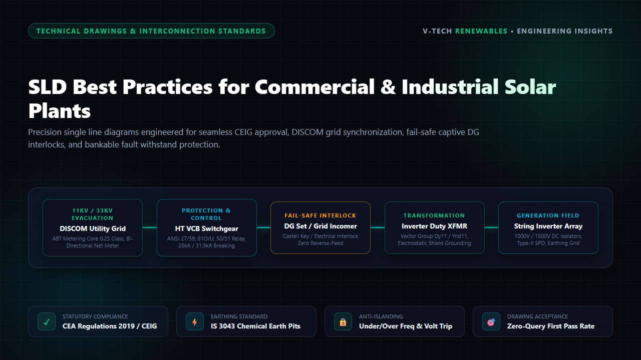
A 2.5 MWp rooftop solar installation in Chakan or Oragadam sits fully wired. Inverters are powered, combiner boxes dressed, and transformers tested. Yet the vacuum circuit breaker stays padlocked shut because the DISCOM inspector rejected an incomplete AutoCAD solar single line diagram (SLD).
In Indian Commercial and Industrial (C&I) solar engineering, an SLD is the binding statutory document reviewed by DISCOMs (MSEDCL, GUVNL, BESCOM, TANGEDCO) and CEIG. Drafting oversights halt plant charging, racking up idle interest and delaying project COD.
The Anatomy of a Flawless C&I Solar Interconnection SLD
C&I solar power plant design mandates strict separation between revenue metering and high-speed protection:
- Dual-Core CT & PT Architecture: Tariff metering cores require Class 0.2S accuracy with 10–15 VA burdens per IS 2705/3156. Protection cores demand 5P10 or 5P20 limits. Combining metering and protection on one core causes immediate file rejection.
- Protection Relay ANSI Codes: Inverter firmware anti-islanding does not replace external switchgear protection. The SLD must show independent numerical relays wired to dual DC shunt trips: 27 (undervoltage), 59 (overvoltage), 81O/U (frequency), 50/51 & 50N/51N (overcurrent/earth fault), and 67 (directional overcurrent).
Captive DG & Grid Interlocking Philosophy
Most C&I facilities operate captive Diesel Generator (DG) sets. Solar generation must never back-feed into running alternators during utility outages, which causes reverse-motoring, governor trips, and engine destruction.
Mandatory Fail-Safe Standard:
Engineers must specify a Castell 2-out-of-3 mechanical key interlock or an electrically monitored PLC lockout, paired with directional reverse power relays (ANSI 32R) set to isolate within 0.1 seconds.
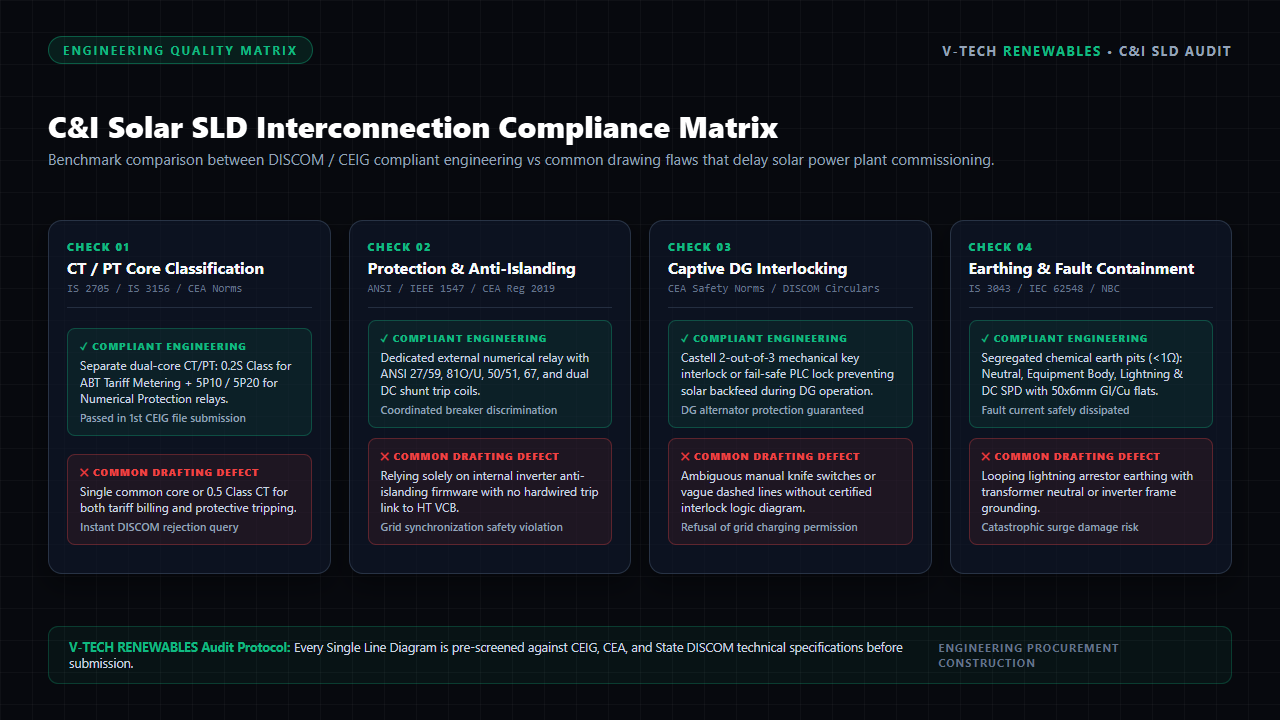
Figure 1: Critical engineering parameters required in C&I Solar SLDs for statutory utility synchronization.
C&I Interconnection Compliance Matrix
Pre-submission drawing audits cut approval cycles from six weeks to under ten days. Below is the statutory benchmark applied across solar EPC execution dossiers:
| SLD Component | Mandatory Specification | Common Drafting Error | Approval Impact |
|---|---|---|---|
| Tariff Metering Core | Class 0.2S dual-core CT/PT, 15 VA | Class 0.5 or shared core | DISCOM Rejection |
| HT Switchgear | VCB 25 kA / 31.5 kA (3s), dual trip | Missing kA withstand rating | CEIG Safety Query |
| DG Interlocking | Castell 2-out-of-3 key interlock + 32R | Manual knife switch | Charging Refused |
| Earthing System | IS 3043 segregated pits (<1 Ω) | Common loop with LA earth | Clearance Withheld |
IS 3043 Earthing & Surge Containment
Per IS 3043 and IEC 62548, the SLD earthing matrix must specify dedicated, physically isolated earth pits with disconnect test links:
- Inverter Body Earthing: Two distinct body earth points per unit using 50×6 mm GI or copper conductor flats.
- Transformer Neutral Earthing: Dedicated low-resistance chemical pits isolated from lightning conductors.
- SPD Grounding: Direct, unlooped low-inductance down-conductors routing surge transients into ground electrodes.
Frequently Asked Questions
1. Why do Indian DISCOMs reject SLDs with shared CT cores for metering and protection?
State DISCOMs mandate Class 0.2S for bidirectional ABT tariff metering to guarantee billing revenue accuracy under varying load conditions. In contrast, protection cores require 5P10 or 5P20 accuracy limits to sustain high fault currents without saturation. Sharing a core compromises tariff precision and risks protection relay failure during short circuits.
2. What interlocking mechanism is mandatory when synchronizing C&I solar with captive DG sets?
To prevent dangerous solar reverse feeding into running diesel generators during utility outages, engineers must implement a fail-safe 2-out-of-3 Castell mechanical key interlock or certified PLC electrical lockout paired with reverse power relays (ANSI 32R).
3. What ANSI protection codes must appear on an 11kV/33kV solar evacuation SLD?
Statutory grid code compliance requires explicit representation of ANSI 27 (Under-Voltage), 59 (Over-Voltage), 81O/U (Over/Under-Frequency), 50/51 (Instantaneous & Time Overcurrent), 50N/51N (Earth Fault), and 67 (Directional Overcurrent) wired directly to the HT vacuum breaker shunt trip coil.
About the Author
Written by the Electrical Design & Interconnection Engineering Team at V-TECH RENEWABLES, Pune—specializing in statutory DISCOM approvals, CEIG drawing audits, and substation engineering across 500+ MWp of solar infrastructure.