Structural Load Calculations: What Every Solar EPC Owner Needs to Know
An industrial manufacturing facility in Pune halts commissioning of its 800 kWp rooftop solar plant. The factory inspector refuses stability clearance. Cold-formed purlins show visible deflection, and roof seams under module arrays warped under seasonal storm gusts.
In C&I solar execution, structural engineering is often treated as clerical paperwork. EPCs rely on generic vendor spreadsheets instead of site-specific load models. When uncalculated dead loads, cleaning traffic, and wind uplift collide, project profits vanish into structural retrofits and CEIG delays.
Where Solar Arrays Overstress Industrial Roofs
Industrial sheds are built with lean steel margins. Purlins and trusses are sized for dead weight and rain drainage, not mechanical fixtures. Three oversights drive structural distress in solar power plant design:
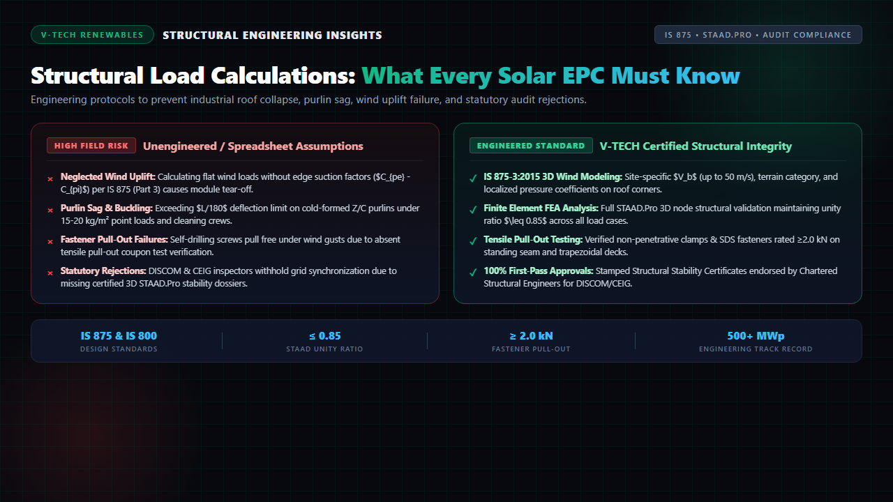
- Concentrated Clamp Point Loads: Modules transfer discrete point loads into light-gauge Z or C purlins, inducing torsional twist and section warping per IS 801.
- Imposed Maintenance Traffic: Under IS 875 (Part 2), roofs must support 0.75 kN/m² access or 1.5 kN concentrated point loads. Robotic cleaners and crew traffic on unsupported sheet spans cause permanent purlin denting.
- Ballast Slab Overloading: On flat RCC roofs, concrete ballast blocks (25–35 kg/m²) placed to avoid membrane punctures frequently breach safe structural live load allowances.
Wind Uplift Realities Under IS 875 (Part 3)
Wind generates the highest failure risk for solar arrays. Under IS 875 (Part 3:2015), basic wind speeds ($V_b$) reach 39–50 m/s across coastal and plateau corridors. Modifying factors ($k_1$ risk, $k_2$ terrain, $k_3$ topography, and $k_4$ cyclonic) amplify design wind pressures substantially.
Airflow separation over eaves and ridges produces intense localized suction ($C_{pe} - C_{pi}$ reaches -1.4 to -2.0). Tables installed without edge setbacks or deflectors experience severe uplift, shearing screws and detaching clamps during solar EPC operations.
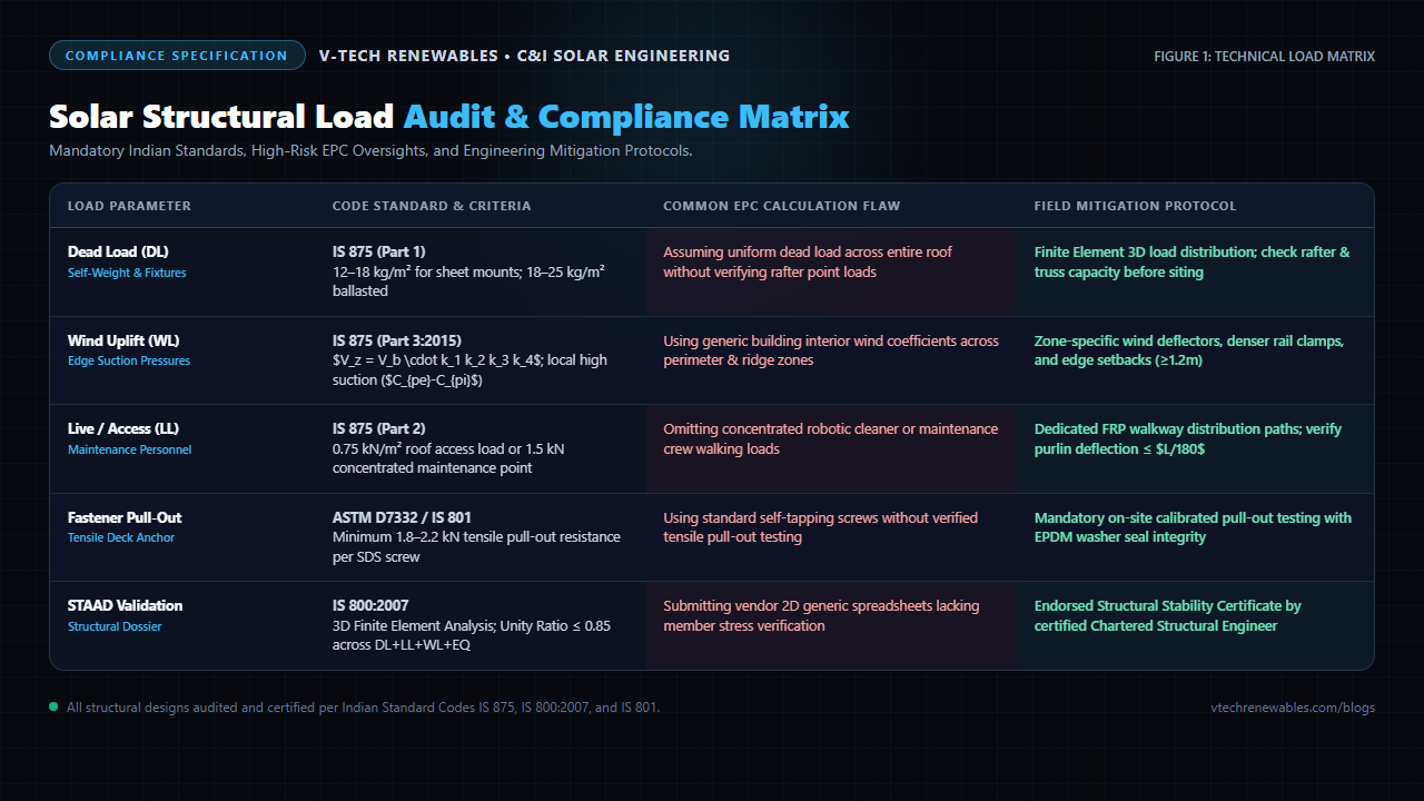
Figure 1: Solar structural load audit and compliance matrix comparing standards, flaws, and field protocols.
Structural Load Audit & Compliance Matrix
Rigorous structural engineering validates every mounting component against statutory design codes:
| Load Case | Code Standard | Common Calculation Flaw | Mitigation Protocol |
|---|---|---|---|
| Dead Load | IS 875 (Part 1) | Assuming uniform spread without rafter checks | Finite Element rafter stress audit |
| Wind Uplift | IS 875-3:2015 | Ignoring ridge and corner suction factors | Zone deflectors & ≥1.2m setbacks |
| Live / Access | IS 875 (Part 2) | Ignoring cleaning crew and robot point loads | Dedicated FRP walkway load distribution |
| Fasteners | ASTM D7332 | Unrated screws without tensile pull-out tests | Calibrated pull-out testing (≥2.0 kN) |
| STAAD FEA | IS 800:2007 | Generic vendor 2D spreadsheet submittals | Chartered Stability Certificate |
Pre-Installation Protocols That Protect Margins
To eliminate site failures, EPCs must enforce three milestones before steel procurement. First, integrate structural evaluations into site survey protocols, logging purlin thickness via ultrasonic gauges.
Second, run complete 3D FEA in STAAD.Pro to confirm unity ratios remain below 0.85 and purlin deflection stays within $L/180$. Third, pair structural reports with standardized solar CAD drafting standards and verified C&I solar SLD practices. This discipline prevents the documentation objections that cause statutory grid drawing delays.
Frequently Asked Questions
1. Why do factory roofs fail structural audits after solar installation?
PEB sheds use light-gauge purlins designed for 50–75 kg/m² live loads. Adding solar dead weight (12–18 kg/m²) and concentrated clamp forces exceeds allowable deflection limits (L/180 per IS 800), failing safety inspections.
2. How does wind uplift under IS 875-3 vary across roof zones?
Airflow separation along eaves and ridges produces suction coefficients (Cpe - Cpi) reaching -1.4 to -2.0—double the center roof. Tables within 1.2m of perimeter edges require heavier clamping and aerodynamic deflectors.
3. When is STAAD.Pro 3D FEA mandatory for solar mounting structures?
CEIG inspectors and factory safety auditors require stamped STAAD.Pro 3D reports for superstructures over 1.5m and C&I projects exceeding 100 kWp, verifying unity ratios under 0.85 across DL, LL, WL, and seismic states.
About the Author
Written by the Structural Engineering Team at V-TECH RENEWABLES, Pune—delivering STAAD.Pro FEA simulations, PEB structural stability certifications, and wind-tunnel-verified module mounting designs across 500+ MWp of solar projects.